Electronic Unit Injector Diagram
Diagram of components for the HEUI fuel system above 1 Unit injector hydraulic pump 2 Oil flow to engine 3 Oil filter 4 Engine oil pump 5 Oil cooler 6 IAP sensor 7 Injectors 8 Fuel supply rail 9 Fuel pressure regulator 10 IAP control valve 11 Fuel filter 12 Fuel tank 13 Back of cam gear 14 Speedtiming sensors 15 ECM 16 Boost pressure sensor 17 Accelerator. The amount of fuel injected and the beginning of injection timing is determined by the ECM.
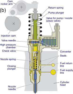
Mechanical Actuated Electronic Controlled Unit Injector
If the overall height is 54 mm 2125 in proceed to step 9.

Electronic unit injector diagram. Position a 0762 mm 0030 in feeler gage between the clamp and injector spring on the side of the spring that faces the intake manifold. When we start the engine the fuel pump will work so that the pressure fuel in. Electronic fuel injector diagram Throttle body injection TBI system Working of electronic fuel injection system The throttle body injection TBI system uses one or two injector valves mounted in a throttle body assembly.
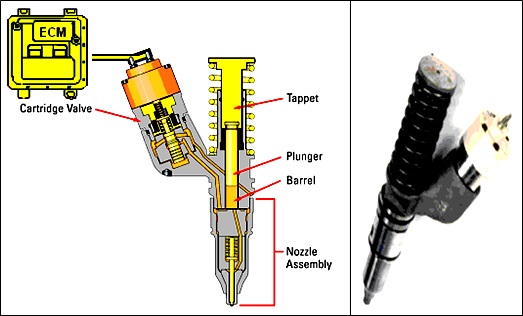
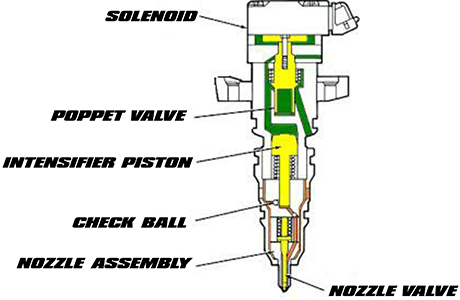
ZEEMS Block Diagram Electrical fuel shut offon propane LPG. Series 60 Electronic Unit Injector Diagram The Electronic Unit Injector EUI is a lightweight compact unit that injects diesel fuel directly into the combustion chamber. The electronic unit injector 30 allows fuel to be injected into the combustion chamber with precise timing.
Conventional Fuel Supply Systems in diesel engines require high-pressure lines to deliver the pressurised fuel into the injectors. Electronic unit injectors are mechanically pressurized using electronic control of governing timing and metering functions. A unit injector UI is a high pressure integrated direct fuel injection system for diesel engines combining the injector nozzle and the injection pump in a single component.
A poppet valve known also as a spill control valve or solenoid needle valve that. Changes in performance are made by installing different software in Electronic Control Module. 67 camaro wiring diagram repair guide diagram mazda radio wiring diagram color code 2 line phone jack wiring diagram vw passat monsoon stereo wiring diagram 150 cf moto 150cc scooter wiring diagram 3 phase hvac compressor wiring straight cable color code wiring dometic a c wire diagram system context diagram ac wiring diagram window air.
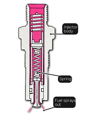
The injector is used to remove fuel into the intake in the form of spray. The spring-loaded plunger and barrel assembly to pressurize fuel inside the injector. So use a larger gauge wire for lower voltage drop.
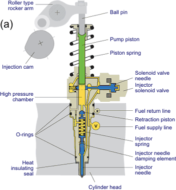
The requirement for more flexible control of injection parameters gave rise to a new form of unit injector called the electronic unit injector in which the traditional P-L-N pumping element design has been replaced by a plain plunger and a high speed electromagnetically solenoid operated spill valve. The ECM sends a command pulse which activates the injector solenoid. If the overall height is 52 mm 2047 in skip to step 10.
High pressure injection delivers power and fuel consumption benefits over. Electronic Fuel Injector Diagram. Electronic Control Unit Fuel Injector Throttle Actuator Distributor Fuel Return gasoline only Fuel Tank propane or gasoline RPM Input Sensors.
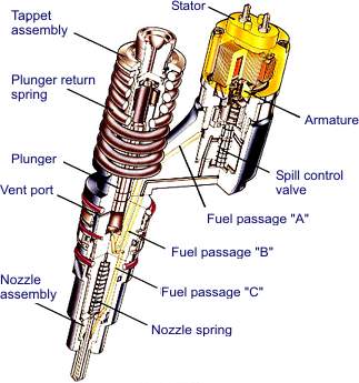
ELECTRONIC UNIT INJECTOR EUI The Electronic Unit Injector EUI injects fuel directly into the combustion chamber. Determine which type of hold-down clamp is used by measuring the overall height. The HEUI fuel system is completely free of adjustment.
Diagram Sistem Bahan Bakar Mechanical actuated Electronic Unit injector MEUIEUI Gambar diatas merupakan komponen diagram EUI. Electronic Fuel Injector Diagram. Electronic Fuel Injection System Diagram and Working Principle Amrie Muchta 3272018 The electronic fuel injection system is a new innovation in gasoline engine this system incorporates electronic computerizm to get the best fuel and air comparisons under all engine conditions.
The operation of the Hydraulic Electronic Unit Injector HEUI fuel system is completely different from any other type of fuel system that is actuated mechanically. Fuel injection system working diagram. Sistem bahan bakar EUI menggunakan supply bahan bakar bertekanan rendah dan kemudian menaikkan tekanan injeksi hingga 10000 sampai 30000 psi.
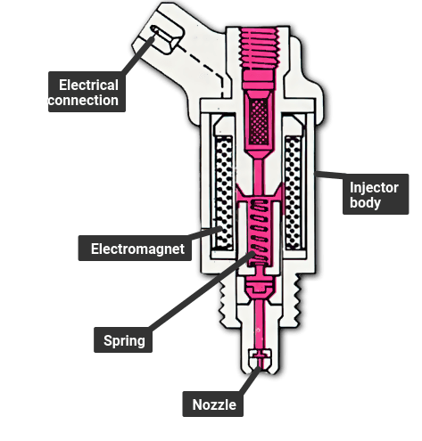
A unit injector consists of several basic elements. The injector is used to remove fuel into the intake in the form of spray. Transferring fuel through.
Adjustments to the components that are mechanical can not be made. N2 Electronic Unit Injector and Related Parts. ZzzEMS Slide 7 ZEEMS ZEEMS COMPONENT LOCATIONS 1.
Fuel System C15 C16 and C18 - Caterpillar Electronic Engine Electric diagram of the basic fuel system typical example 1 Electronic unit injector 2 Solenoid for the fuel injection pump 3 Wastegate solenoid if equipped 4 Position sensor fuel injection pump 5 Fuel injection pump 6 Crankshaft position sensor 7 Boost pressure sensor 8 Fuel pressure sensor 9 Engine oil. The small size of the injector along with the trapezoidal valve placement in the cylinder head allows the EUI to be placed in the center of the combustion chamber for optimal fuel efficiency and low emissions. What Are Benefits Of Electronic Fuel Injection Efi Fuel Injection.
TB COOLANT FITTINGS 9. It performs the same function as a conventional unit injector in an internal combustion engine such as in an on-road or off-road vehicle or a diesel-electric locomotiveThe pressurized delivery of fuel is camshaft-driven but the timing of the injectors internal operations are controlled by the. The plunger pump used is usually driven by a shared camshaftIn a unit injector the device is usually lubricated and cooled by the fuel itself.
An electronically controlled unit injector EUI is a unit injector UI with electronic control. The system controller adjusts when and how long the injector opens.
Unit Injector And Unit Pump Systems
Injection System Components Types And Working Principles Ingenieria Y Mecanica Automotriz

Electronic Fuel Injection Systems For Heavy Duty Engines

Delphi E3 Diesel Electronic Unit Injector Pdf Free Download
Electronic Fuel Injection Systems For Heavy Duty Engines

3100 Heui Diesel Truck Engine Hydraulic Electronic Unit Injector Caterpillar Engines Troubleshooting

Unit Injector And Unit Pump Systems
How A Fuel Injection System Works Breeze Oil Changes
How Heui Injectors Work
Fuel System Overhaul

How A Fuel Injection System Works Une Voiture
Series 60 Section 2 5 N3 Electronic Unit Injector Detroit Diesel Engine Troubleshooting

Schematic Of Ceup Fuel Injection System Download Scientific Diagram

Series 60 Section 2 3 N2 Electronic Unit Injector Detroit Diesel Engine Troubleshooting

Unit Injector And Unit Pump Systems
Fuel Injectors Pumps Section 1 1 Diesel Fuel System Overview Detroit Diesel Engine Troubleshooting

Electronic Fuel Injection System Parts Types Working Advantages

Unit Injection Automobile
Unit Injector And Unit Pump Systems


Post a Comment for "Electronic Unit Injector Diagram"